Adjustable Lighting Device
Several objects and advantages of the present invention are:
- to increase light resolution and efficiency of the lighting device with elongated high efficiency fluorescent lamps and provide adjustable light distribution in space.
- to provide a lighting device, which is characterized by low weight, simplified construction and low production cost as a result of using light reflectors made of film and rotatable around the body of elongated tubular fluorescent lamp, acting as rotation axis for
reflectors.
Further objects and advantages are to provide:
- rigidity of reflectors made of film by using of spacers disposed in the direction of longitudinal axis of the lamp;
- stability of the form of reflectors made of film, by using stiffeners; - permanency and rigidity of reflectors made of film, and at the same time, increase in efficiency of the lighting device by excluding of shading light flow by the body of lamp;
- protection of tubular fluorescent lamp from mechanical impacts and pollutions, using light-transparent tube as mechanical rotation axis for reflectors;
- protection of reflecting surface of reflectors from mechanical impacts, pollutions, weather conditions by using light-transparent window, which might bear decorative functions and at the same time, act as a disperser and/or concentrator of light flow.
- reflectors, which are easy and convenient in installation/dismantling and exploitation by making them as
separatable, constructions.
Still further objects and advantages will become apparent from a consideration of the ensuing description, taken in conjunction with the accompanying drawings, in which like reference characters refer to like parts throughout.
Brief description of the drawings
FIG.1A is a general view of the first embodiment of a lighting device according to the invention, with brackets for holding reflectors, which are mounted on fluorescent
tube.
FIG.1B and Fig.1C are various cross sectional views of the lighting device, shown in
FIG.1A.
FIG.2 is a general view of the second embodiment of a lighting device according to the present invention, without brackets, holding reflectors.
FIG.3A is a general view of the third embodiment of a lighting device according
to the present invention, with spacers, used to attain (provide) rigidity of thin-walled
reflectors.
FIG.3B is a cross sectional view of the lighting device, shown in
FIG.3A.
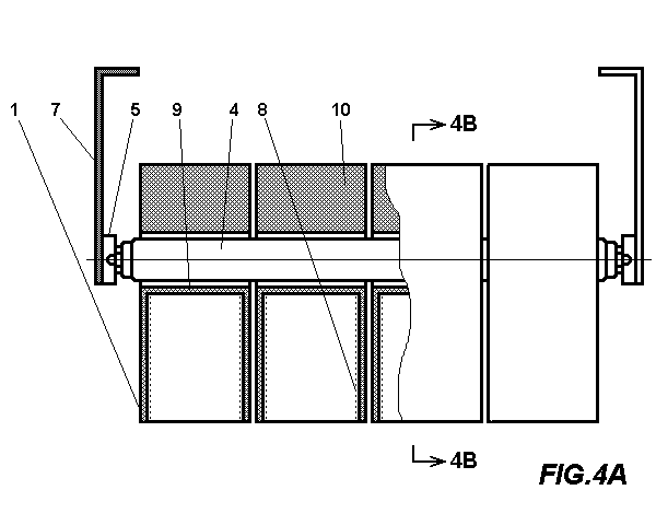
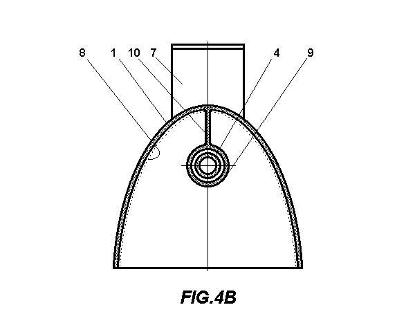
FIG.4A is a general view of the fourth embodiment of a lighting device according
to the present invention, with stiffeners, increasing mechanical rigidity of thin-walled reflectors.
FIG.4B is a cross sectional view of the lighting device, shown in
FIG.4A.
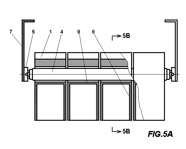
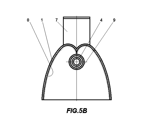
FIG.5A is a general view of the fifth embodiment of a lighting device according to the present invention, with stiffeners, made by profiling walls of reflectors.
FIG.5B is a cross sectional view of the lighting device, shown in
FIG.5A.
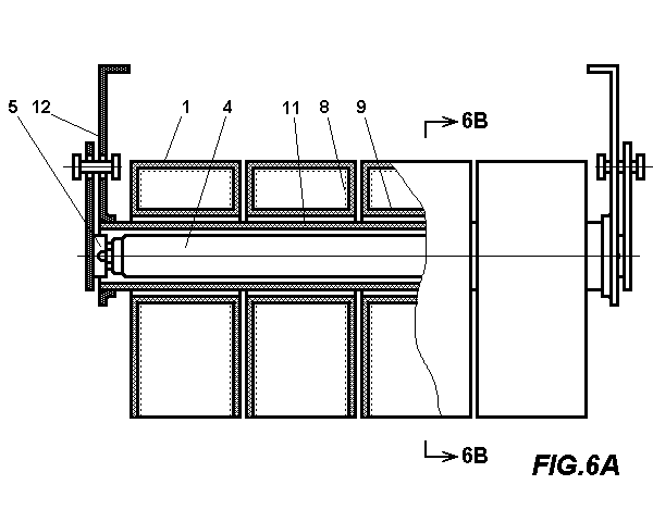
FIG.6A is a general view of the sixth embodiment of a lighting device according to the present invention, with a light-transparent tube used as rotation axis for reflectors.
FIG.6B is a cross sectional view of the lighting device, shown in
FIG.6A.
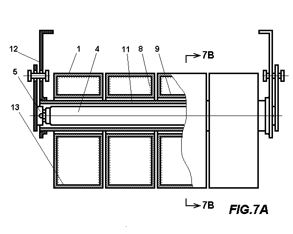
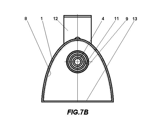
FIG.7A is a general view of the seventh embodiment of a lighting device according to the present invention, with reflector, furnished with light-transparent windows.
FIG 7B is a cross sectional view of the lighting device, shown in
Fig 7A.
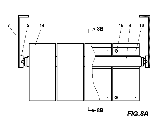
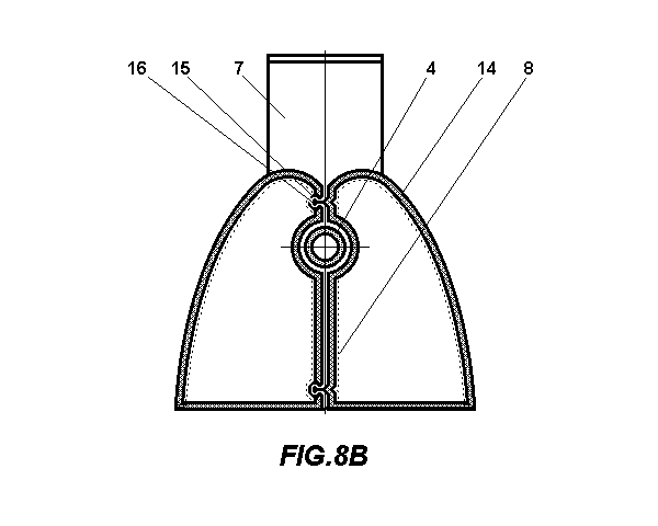
FIG.8A is a general view of the eighth embodiment of a lighting device according to the present invention, with reflector, consisting of two half-reflectors, mounted onto fluorescent tube.
FIG.8B is a cross sectional view of the lighting device, shown in
Fig 8A.ĀĀ
Reference Numerals in Drawings
1 reflector
2 brackets
3 tenons
4 tubular fluorescent lamp
5 sockets
6 brackets
7 brackets
8 metal coating |
9 spacer
10 stiffener
11 light-transparent tube
12 brackets
13 light-transparent window
14 half-reflectors
15 cavities
16 knobs |
Description of embodiments of the invention
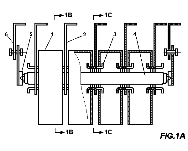
FIGS 1A-1C show the first embodiment of the invention.
FIG.1A is a general view of a lighting device which reflectors
1 are held by brackets 2, with deflected tenons 3, so that the centers of the apertures in reflectors
1 and brackets 2 are located on the same axis, which coincides with the longitudinal axis of fluorescent tube
4. Tubular fluorescent lamp 4 is passed through apertures in brackets
2 and reflectors 1, and fixed in sockets 5, which are disposed on spring hinged brackets
6. Brackets 6 comprise two hinged spring flat bars, which allow to deflect sockets
5 away from the lighting device, when it is necessary to install and replace lamp. Each of reflectors
1 rotates by any angle around the longitudinal axis of fluorescent lamp
4 to direct light from the corresponding part of illuminating cylindrical surface of fluorescent lamp
4 to desirable area of the interior. FIG.1B and
FIG.1C are various cross sectional views of lighting device, showing the interaction of the
components.
In order to lower mechanical load on the fluorescent lamp
4, produced by weight of reflectors 1, the reflectors might be made of thin (preferably, 0.2 to 1 mm thickness) polymeric film.
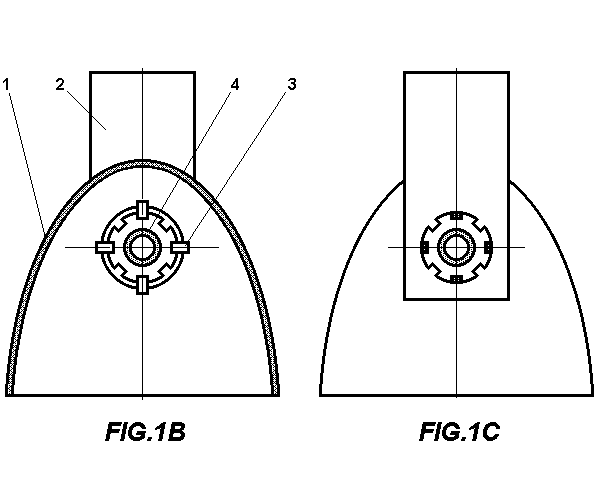
FIG.2 illustrates another embodiment of the invention, showing its general view. Reducing the weight of reflectors, for instance, by making them from plastic film, makes possible direct installation of reflectors onto cylindrical body of fluorescent lamp
4 with no brackets for holding reflectors. Reflectors 1, made preferably of plastic film, are simply threaded onto fluorescent lamp
4, and retained thereon in a given position by friction force, defined by the tightness of fitting apertures in reflectors
1 to cylindrical surface of fluorescent lamp 4. Fluorescent lamp
4 with so-mounted reflectors 1 is thereafter placed in sockets
5, disposed on brackets 7. This simplified design provides increase in efficiency of the lighting device due to reducing losses on joints of neighboring reflectors and reduces cost of the lighting device. In order to give reflecting properties to the surface of reflector
1, the film is coated by metal coating 8.
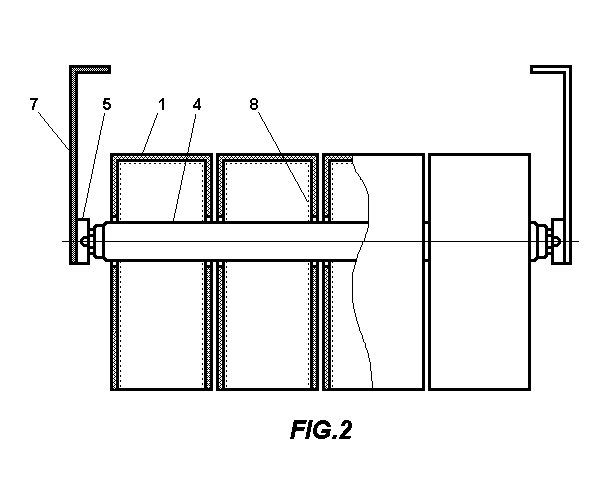
FIG.3A and FIG.3B demonstrate another embodiment of the invention. In order to attain permanency of form and rigidity of thin-walled reflectors (they are less stable in comparison with reflectors made of glass or metal) along the longitudinal axis of fluorescent lamp
4, a light-transparent spacer 9 is included into a reflector's design.
FIG.3A is a general view, and FIG.3B is a cross sectional view of the lighting device with reflectors
1, made of light-transparent, plastic film, covered with metallized coating
8. Each of reflectors 1 comprises the spacer 9. This spacer
9 might be made of light-transparent plastic material together with the body of the reflector
1 in the same technological cycle. Unlike the rest part of reflector
1, the spacer 9 is not
metallized.
To increase rigidity of the back walls of reflectors (the side, opposite to the direction of emitted light flow) a stiffener
10 is included into a construction of reflector. In FIG.4A and
FIG.4B, illustrating another embodiment of the invention, the stiffener
10 is placed in a plane of symmetry of the reflector 1. This plane coincides with longitudinal axis of the fluorescent lamp
4.
FIG.5A and FIG.5B demonstrate an alternative embodiment of the invention, where the stiffener
10 is made by profiling the wall of the reflector 1 so that the walls of reflector acquire a predetermined curvature shape, for example, involute.
FIG.5A is a general view, and FIG.5B is a cross sectional view of the lighting device, where the profile of the back wall of the reflector
1 is given a shape of involute. Profiling the back wall of reflector
1 increases its rigidity. As additional advantage, this particularly profile makes the lighting device more efficient, producing higher light output from the surface of fluorescent lamp
4, because the light reflected by reflectors 1, is not shaded by the body of fluorescent lamp
4.
FIG.6A and FIG.6B show the next embodiment of this invention. The fluorescent lamp
4 is placed into light-transparent tube 11, fastened in brackets
12 and used as mechanical rotation axis for reflectors 1, so that the reflectors
1 are rotated around the tube 11. The tube 11 bears protective functions, especially when the lighting device is disposed in open air in natural weather conditions. Embraced by the tube
11, the fluorescent lamp 4 is:
-released from mechanical tension, produced by the weight of reflectors, which is important if the reflectors
1 are made of glass or metal,
-protected from pollution, vibrations and atmospheric impacts, thereby providing additional
safety of the lighting device.
FIG.7A and FIG.7B show another embodiment of the invention, illustrating the alternative design of reflector, made in the form of hermetic closed chamber, with light-transparent window
13 on one side of reflector 1. This window 13 is included into a design of reflector in order to further increase rigidity of reflector
1, and in addition, protects reflecting surface of reflector 1 from pollution, mechanical and atmospheric impacts. The reflector
1 in this embodiment is made of light-transparent film, and therefore, does not prevent light illuminating from reflecting surface, to pass through.
FIG.7A is a longitudinal view, and FIG.7B is a cross sectional view of the lighting device with closed reflectors, furnished by window
13. Simultaneously, this light-transparent window 13 might function as a disperser and/or light concentrator, if for instance, on the surface of the light-transparent window
13 it will be created a definite pattern, consisting of sequences of concaves and bulges with predetermined shape, so that the window
13 is given definite optical properties. The profile of the window
13 might also be dictated by decorative purposes, for instance, reflector
1 might imitate a shape of motorcycle headlight, and light-transparent window
13 imitates headlight lens of this headlight.
FIG.8A and FIG.8B demonstrate an advantageous embodiment of the invention, which significantly simplifies the procedures of installation and dismantling of reflectors. This is achieved by making reflectors from two half-reflectors
14, embracing the body of the fluorescent lamp 4. The two half-reflectors
14 are fastened with each other by snaps, formed by cavities 15 and knobs
16 on the bodies of half-reflectors 14, so that each reflector is simply assembled directly on already installed fluorescent lamp
4 by clicking snaps without dismantling lighting device.
|